VMware introduced VRF capabilities in NSX-T 3.0, this post will guide you how through the steps to configure and enabled VRF capabilities.
A virtual routing and forwarding (VRF) gateway makes it possible for multiple instances of a routing table to exist within the same gateway at the same time. VRFs are the layer 3 equivalent of a VLAN. A VRF gateway must be linked to a tier-0 gateway. From the tier-0 gateway, the VRF gateway inherits the failover mode, Edge cluster, internal transit subnet, T0-T1 transit subnets, and BGP routing configuration.
If you are using Federation, you can use the Global Manager to create a VRF gateway on a tier-0 gateway if the tier-0 spans only one location. VRF gateway is not supported on stretched tier-0 gateways in Federation
Prerequisites
We are going to need some base work done before configuring and enabling the VRF configurations
- Deploy at least one Edge VM or Bare Metal appliance
- Create an Edge Cluster and add the Edge VM or BM appliance to the cluster
- Create a T0 in the networking section
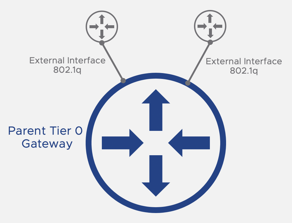
- A Trunk Segment is required as the uplink interface on the Edge VM as each VRF created will consume a VLAN on the trunk between the T0 and the TOR
- The VLAN used in the uplink interfaces in the Parent T0 should not overlap with any of the networks within VRF’s – make sure to use a unique VLAN not included in the trunk segment used by the VRF Interfaces.
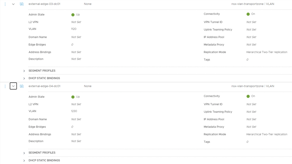
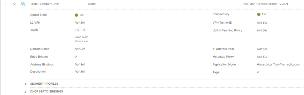
I will be using VLAN’s 1110-1119 for VRF’s uplink interfaces mapped to EDGE-03 and VLAN’s 1220-1229 for VRF’s uplink interfaces mapped to EDGE-04
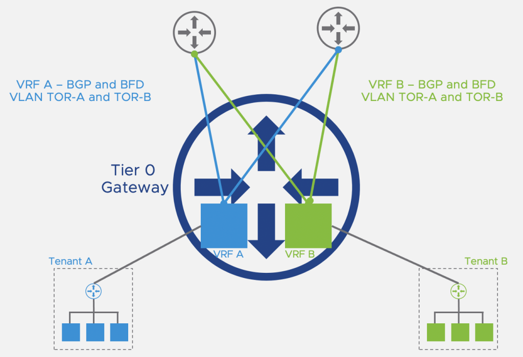
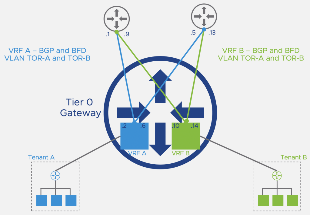
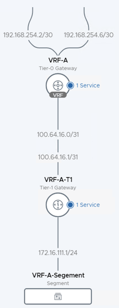
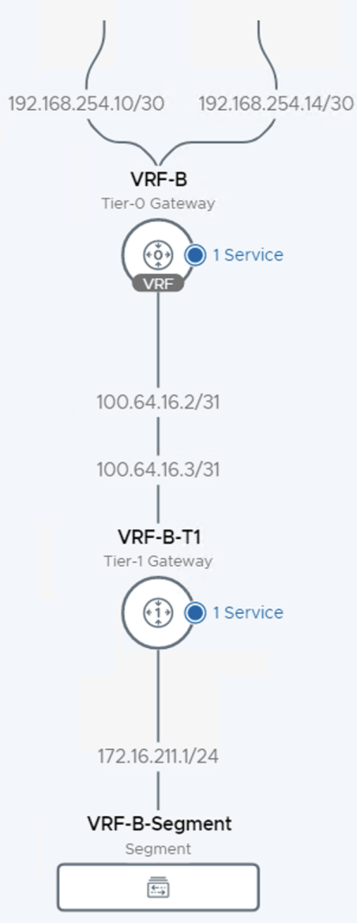
Once we have completed the configurations our desired topology would have two VRF’s configured shown below
Lets get started
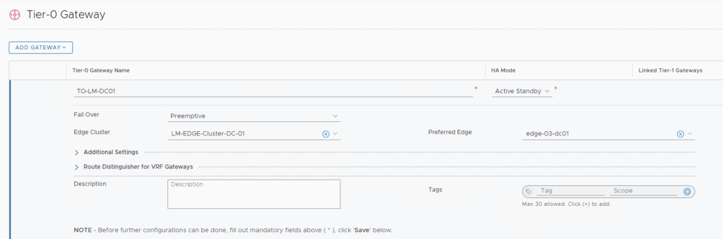
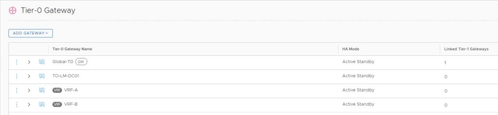
Select Networking > Tier-0 Gateway I am using TO-LM-DC01 in my setup.
Click Add Gateway > VRF, then name the new VRF T0 Gateway and assign it to the T0 pre-created (T0-LM-DC01 in my lab).

Repeat this step for VRF B and you should have created two new T0’s named VRF-A and VRF-B
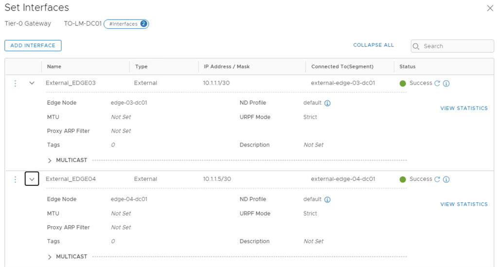
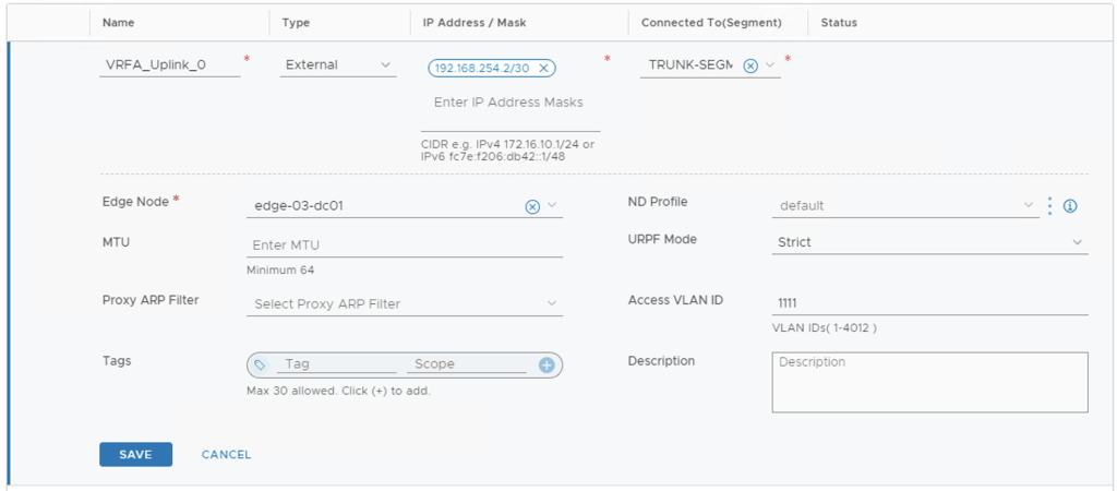
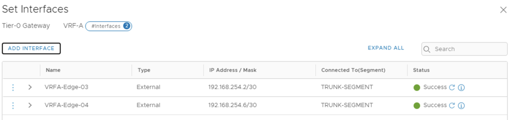
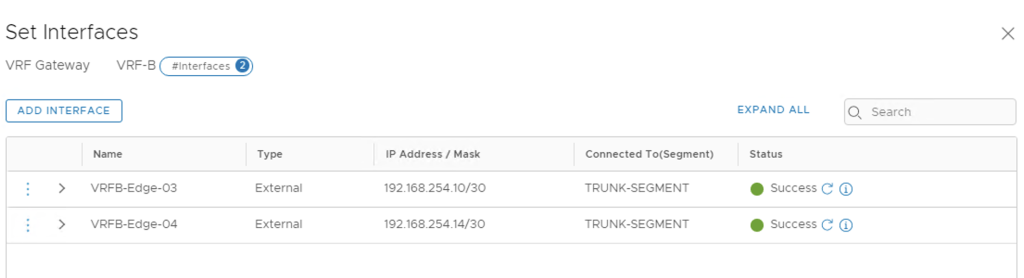
Next we will configure the uplink interfaces to TOR for each VRF created.
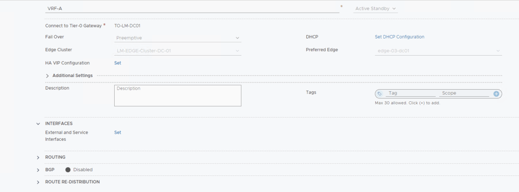
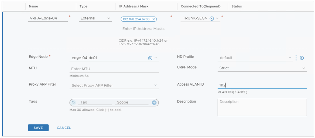
My Edge Cluster has two Edge VM so I will need to create two Interfaces per VRF T0 and these will be need to mapped to the correct access VLAN configured on the TOR
EDGE-03-DC01 VRF A – 192.168.254.0/30, access VLAN 1111
EDGE-04-DC01 VRF A – 192.168.254.4/30, access VLAN 1112
EDGE-03-DC01 VRF B – 192.168.254.0/30, access VLAN 1221

EDGE-04-DC01 VRF B – 192.168.254.4/30, access VLAN 1222

Next Step will be enabling BGP between the VRF T0’s to the TOR
The VRF TO’s will use the same BGP AS Number created in the parent TO, in my case I have reconfigured this to 65111 at the parent.
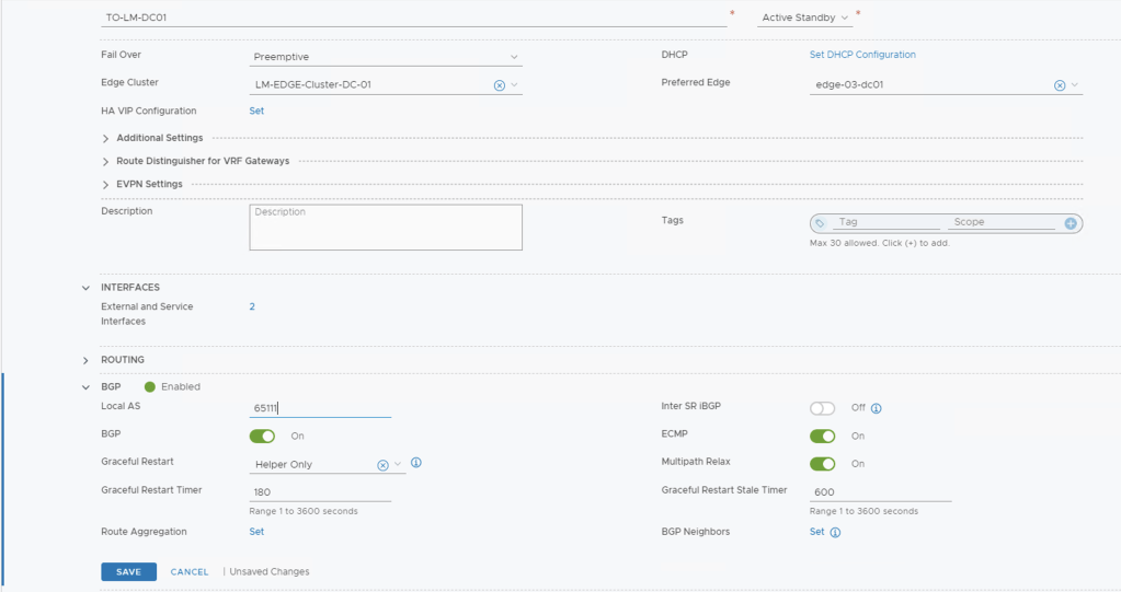
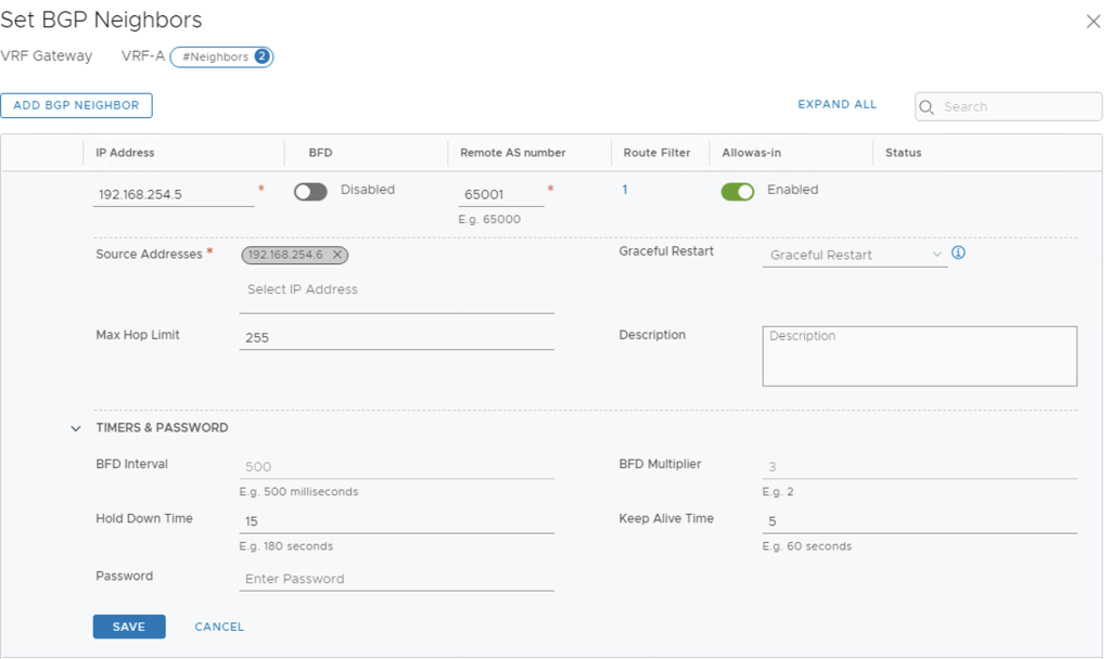
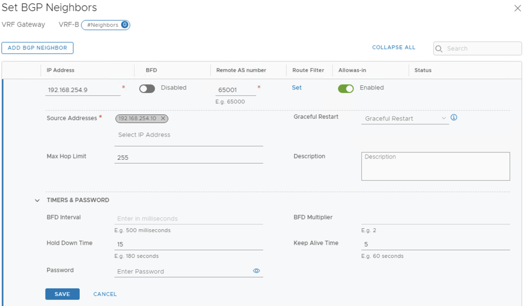
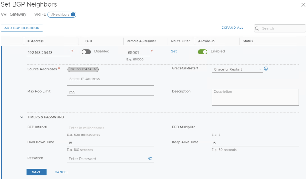
Next Step is to enable BGP on each VRF T0
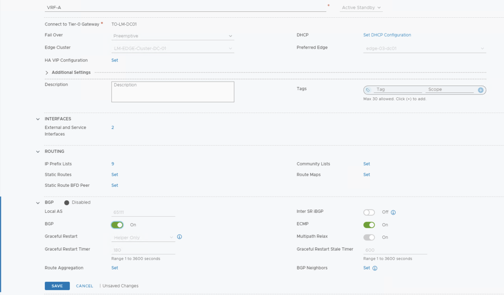
Now go ahead and click set to add your BGP Neighbours

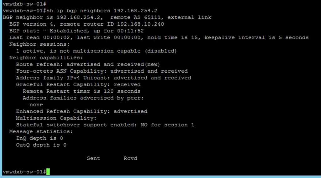
After enabling BGP to the TOR and the BGP neighbour relationship is established, you should see success status in the dashboard
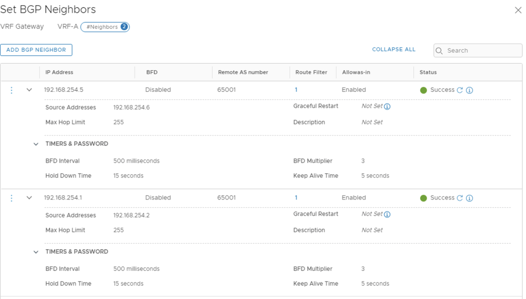
This can be confirmed from TOR, where the BGP neighbour status should show established
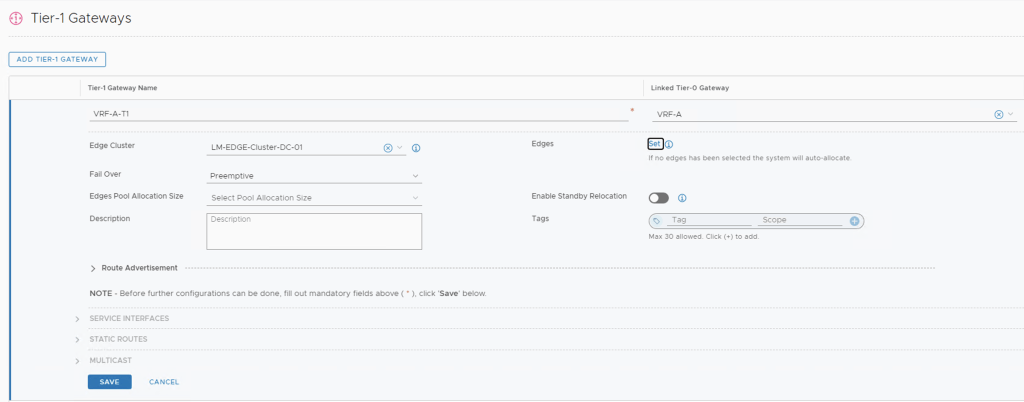
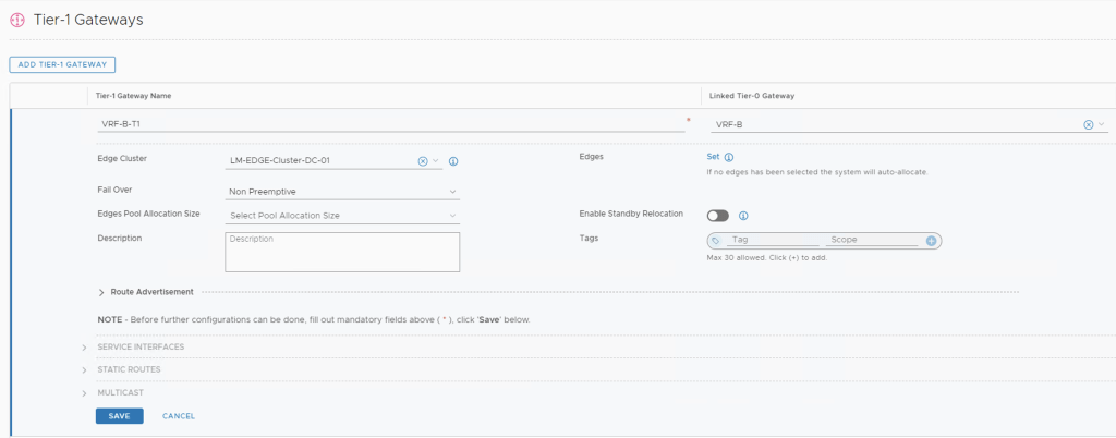
Adding T1’s to the VRF enabled T0
Next will create two T1’s, one for VRF A and the other VRF B and will attach these to the T0’s created. This is where we will attach our VRF workload networks.
Enabling BGP on the T0
Once the T1’s are created we can edit the routing attributes to automatically advertise the networks attached to the T1. This will also BGP to automatically advertise the newly created networks to the TOR switches. Since this is just a lab set up, I have enabled all the options – I can edit these as I enable stateful services if I want to control how I advertise my connected interfaces.
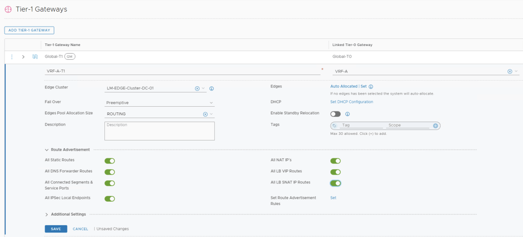
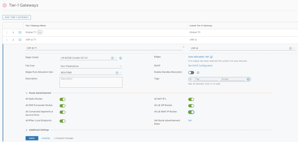
***We will need to make sure we have enabled Router Advertisement on the VRF T0’s towards the TOR too***
Adding Segments to the T1
Now we will add a segment to each VRF T1 so that we can connect our workloads to and confirm we have connectivity to the outside world.
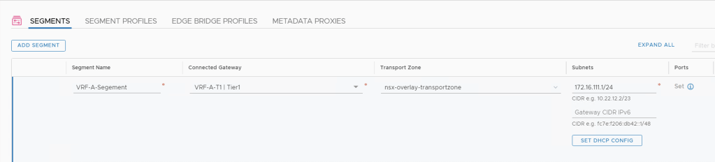
We create the segment and attach it to the correct T1 Gateway, either VRF A or VRF B and I selected to deploy this an Overlay Segment.
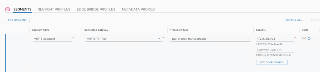
After creating the segments, I can see them in the NSX-T dashboard and confirm that they have been attached to the correct T1’s and review the network topology.

From the NSX-T topology view I see all my uplink IP’s and the segment which I attached to the T1
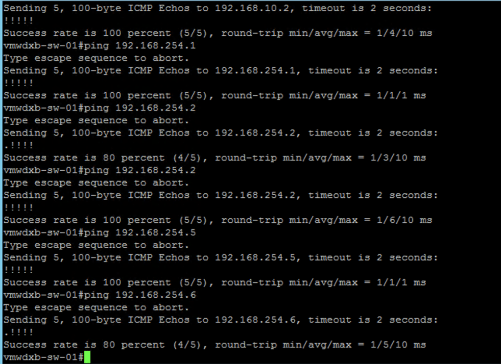
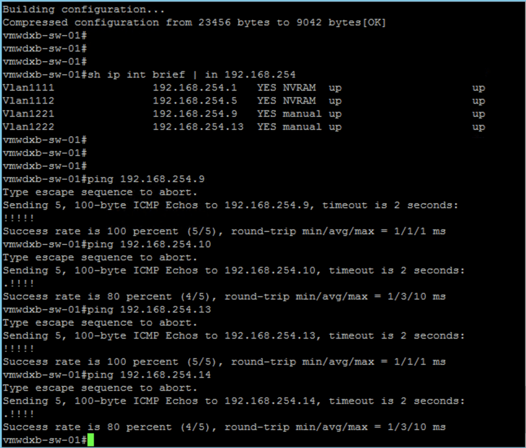
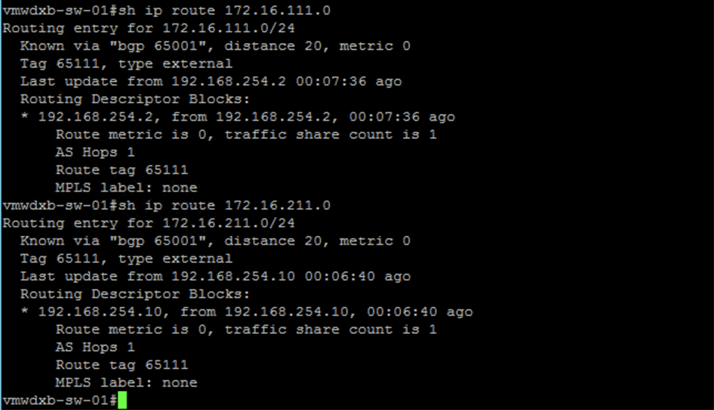
Lastly I want to connect to the TOR and confirm that these newly create IP subnets are being advertised from NSX-T to the TOR via BGP
IP Connectivity to the newly created subnets
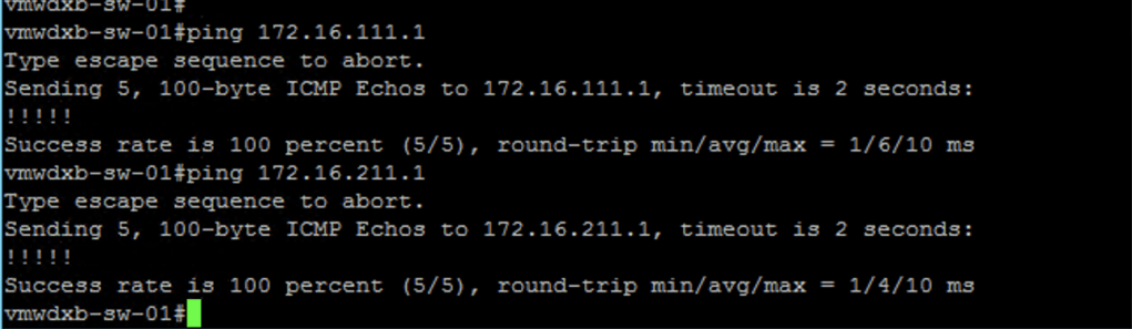
Now lets us the NSX-T Traceflow troubleshooting tool to confirm we have end to end connectivity by doing a trace from a VM connected to VRF-A to another VM connected to VRF-B
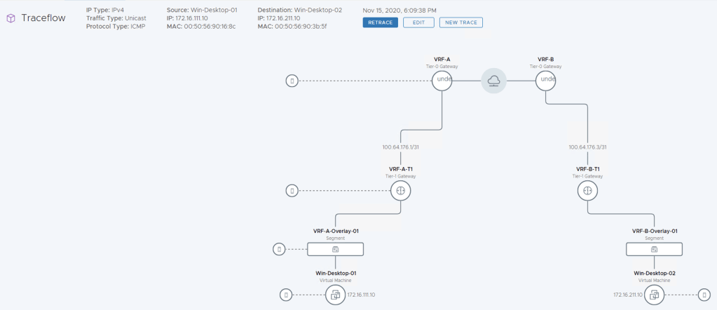
I hope you found this useful. Thanks
