
VMware recently announced the general availability of NSX-T 3.1.0 bringing a host of new features and functionality. One of the key features which is now production ready is the Multi-Site solution, Federation.
- Support for standby Global Manager Cluster
- Global Manager can now have an active cluster and a standby cluster in another location. Latency between active and standby cluster must be a maximum of 150ms round-trip time.
- With the support of Federation upgrade and Standby GM, Federation is now considered production ready.
With Federation, you can manage multiple NSX-T Data Center environments with a single pane of glass view, create gateways and segments that span one or more locations, and configure and enforce firewall rules consistently across locations.
Once you have installed the Global Manager and have you added locations, you can configure networking and security from Global Manager.
In this post I will cover the step by step process to connect my two Local Managers (LM’s) to a Global Manager (GM). I have pre deployed both local sites and the Active/Standby GM appliances.
For a better understanding on the features which are supported or not supported when using NSX-T Data Center Federation, see VMware’s guide.
Lets get started
Pre Work Check List
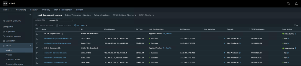
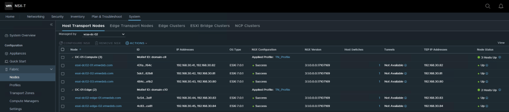
- NSX-T Local Managers deployed and hosts prepared for NSX
- NSX-T Local Managers backup configured and executed
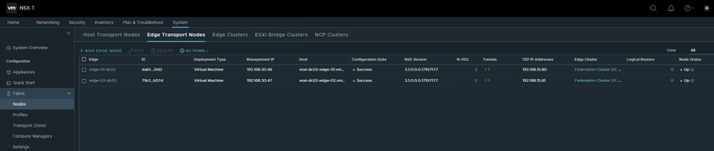
- NSX-T Edge(s) deployed in Local Manager and Edge Clusters created
- Local Manager requires Enterprise Plus License


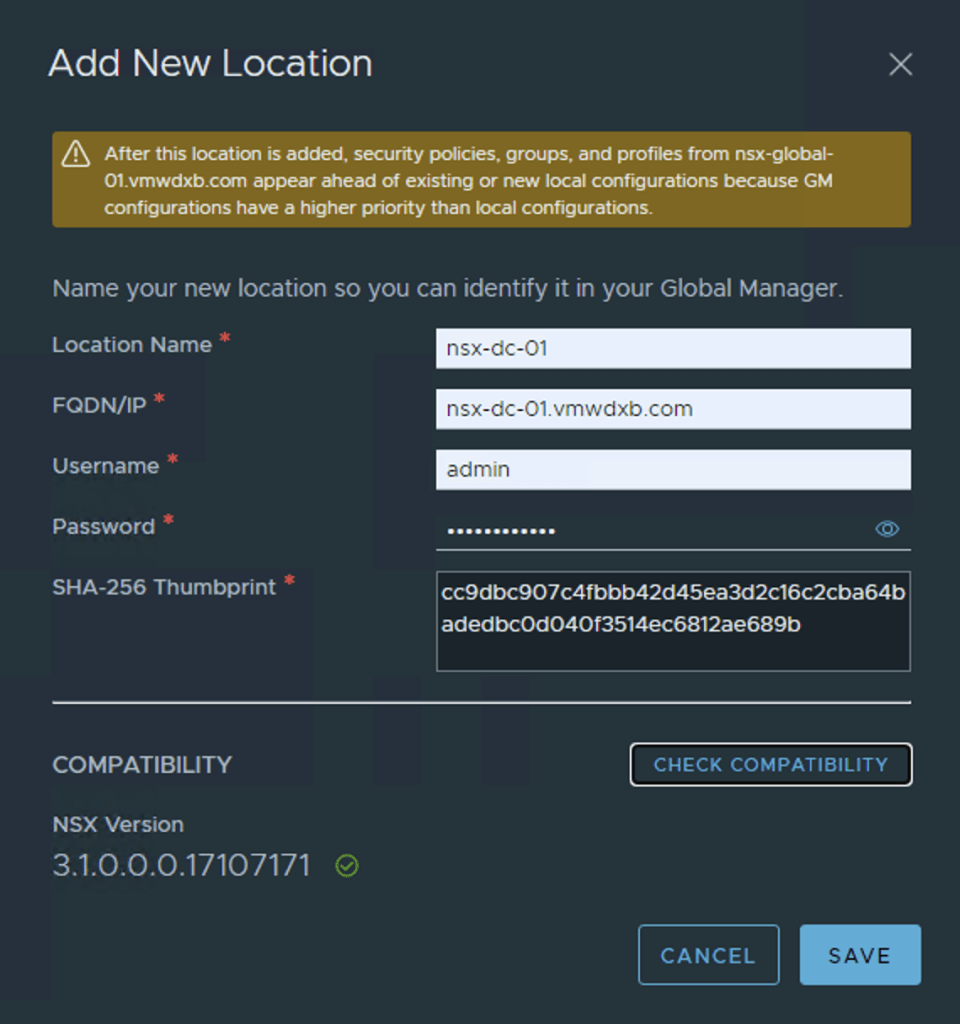
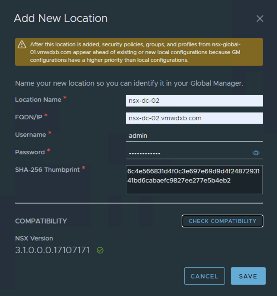
Now lets start adding the first Local Manager nsx-dc-01 under the Location Manager tab. Populate the required details for the local manager. Check Compatibility and hit save. The Local Manager should be on the same OS level as the Global Manager.
Next step would be to add the next sites local manager – nsx-dc-02 in my setup.
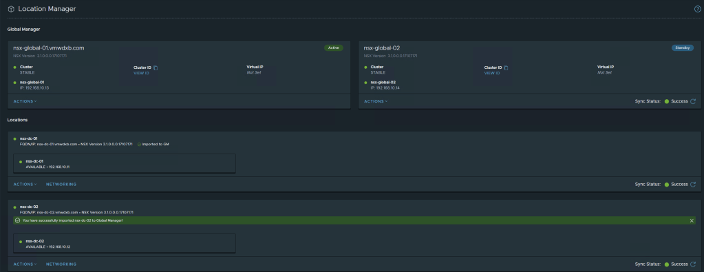
Once both Local Managers have been added and the Global Manager dashboard is refreshed you will see both Local Managers in the Global Manager dashboard.
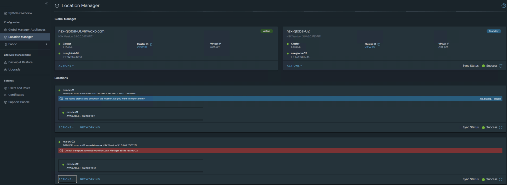
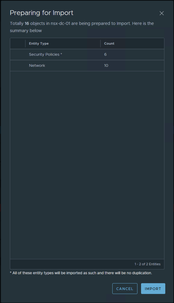
After adding the two Local Managers my Global Manager highlights that is has found objects and policies in these newly added locations and asks Do you want to import them. ***This is a one time option and can not be done after proceeding***
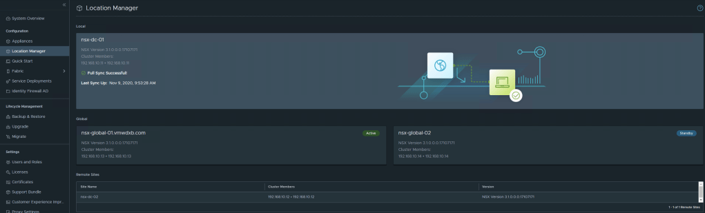
Confirm Local Manager successfully registered to GM
Log into the two Local Managers and see the status and view from the Local Managers, you will notice that the LM’s establish connection to the Active and Standby GM’s as well a connection is established to the neighbour LM’s

Now I will go ahead an import the objects which the GM discovered in LM from DC-01. At this point the GM will check if a configuration backup of the LM manager has been taken before it will proceed with the import. If a backup has not been taken, the step can not proceed.

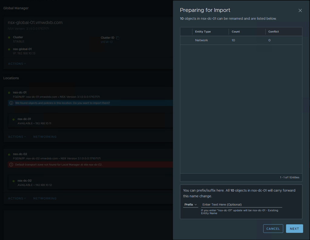
You can add a Prefix or Suffix to the imported objects – this is optional
Once this is completed for the first LM, I refreshed the dashboard and the GM requests the same for my second LM

I just followed the same steps and imported the discovered objects.
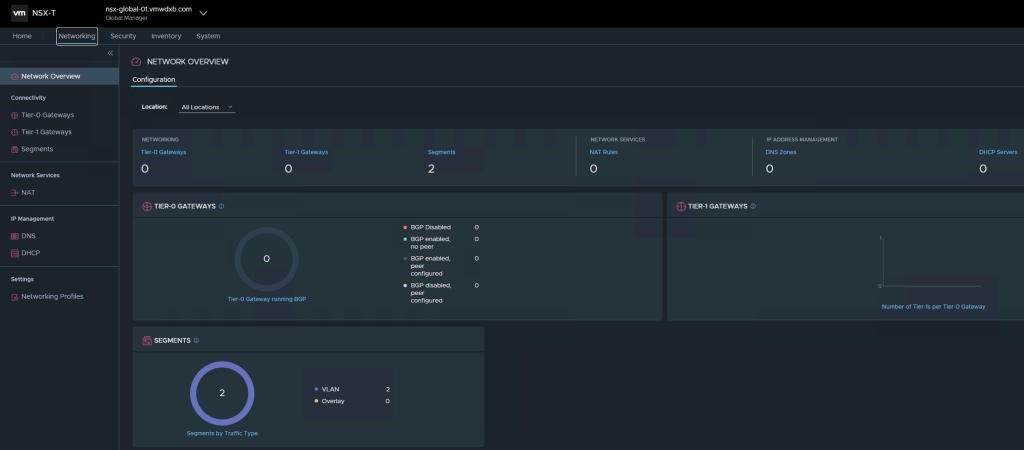
Networking in Federation
Federation enables you to create virtual network topologies spanning multiple locations across L3 connected networks.
Take Note of the following
Tier-0 gateways, tier-1 gateways, and segments can span one or more locations in the Federation environment. When you plan your network topology, keep these requirements in mind:
- Tier-0 and tier-1 gateways can have a span of one or more locations.
- The span of a tier-1 gateway must be equal to, or a subset of, the span of the tier-0 gateway it is attached to.
- A segment has the same span as the tier-0 or tier-1 gateway it is attached to. Isolated segments are not realized until they are connected to a gateway.
You can create different topologies to achieve different goals.
- You can create segments and gateways that are specific to a given location. Each site has its own configuration, but you can manage everything from the Global Manager interface.
- You can create segments and gateways that span locations. These stretched networks provide consistent networking across sites.
Configuring Remote Tunnel Endpoint on the Edge
If you want to create gateways and segments that span more than one location, you must configure a remote tunnel endpoint (RTEP) on Edge nodes in each location to handle the cross-location traffic.
NSX-T Federation introduces a Remote Tunnel Endpoint (TEP) Interface on the NSX Edge which is used to transport encapsulated data between the Local Manager locations. This reduces the amount of inter site TEP’s which was normally built between transport nodes.
All Edge nodes in the cluster must have an RTEP configured. You do not need to configure all Edge clusters with RTEP. RTEPs are required only if the Edge cluster is used to configure a gateway that spans more than one location.
You can also configure RTEPs from each Local Manager. Select System > Get Started > Configure Remote Tunnel Endpoint.
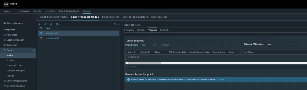
You can edit RTEPs on an Edge node. Log into the Local Manager and select System > Fabric > Nodes > Edge Transport Nodes. Select an Edge node, and click Tunnels. If an RTEP is configured, it is displayed in the Remote Tunnel Endpoint section. Click Edit to modify the RTEP configuration.
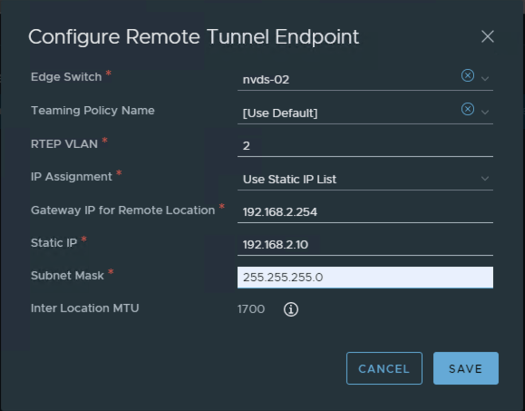
I am using nvds-02 which is mapped to my vlan-transport zone and my Interface is mapped to VLAN 2 on my switch in DC-01 and vlan 3 for DC-02. I have just used static IP assignment. This task is repeated for Edge appliance which we will be using for the Edge Cluster in our Global Networking setup.
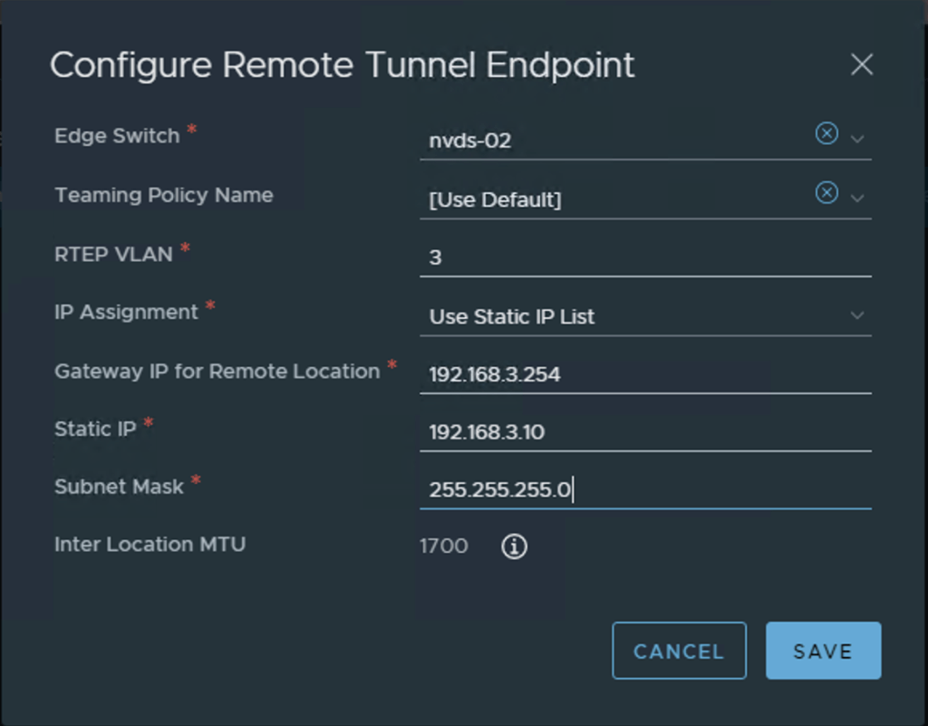
Configure the MTU for RTEP on each Local Manager. The default is 1700. Set the RTEP MTU to be as high as your physical network supports. On each Local Manager, select System > Fabric > Settings. Click Edit next to Remote Tunnel Endpoint. The RTEP can work using an MTU of 1500 but will cause fragmentation.
Tier-0 Gateway Configuration in Federation
Federation offers multiple deployment options when considering T0 deployment and configuration – Active/Active or Active/Standby with some variations of each. As with any Active/Active deployment in NSX-T at the T0, stateful services are not supported.
I have opt for the following deployment in my setup
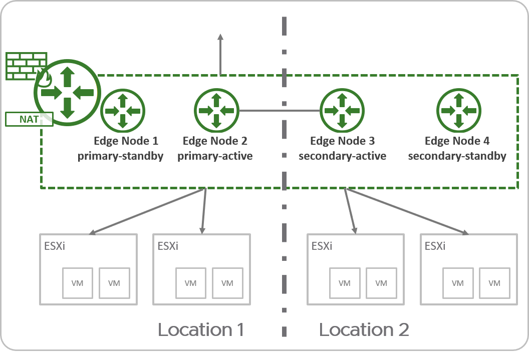
In an active-standby tier-0 gateway with primary and secondary locations, the following applies:
- Only one Edge node is active at a time, therefore the tier-0 can run stateful services.
- All traffic enters and leaves through the active Edge node in the primary location.
For Active Standby tier-0 gateways, the following services are supported:
- Network Address Translation (NAT)
- Gateway Firewall
- DNS
- DHCP
Refer to Tier-0 Gateway Configurations in Federation for all the deployment options and considerations.
Lets go ahead and create our T0 in the global manager

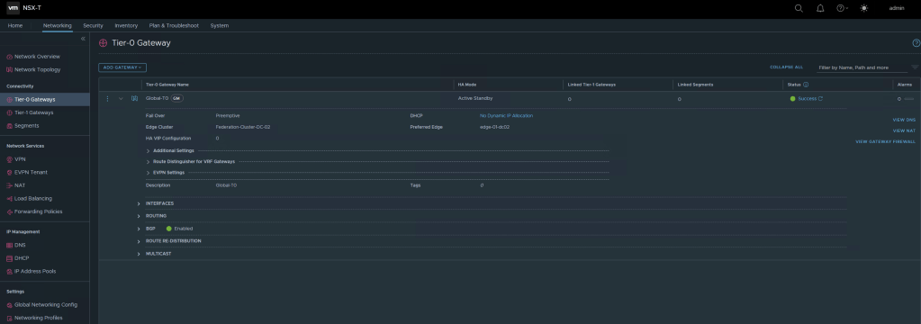
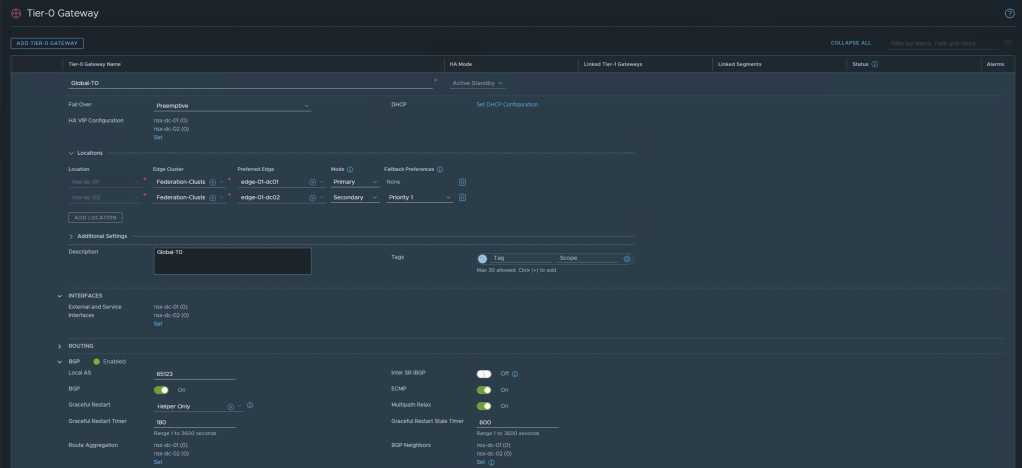
I am creating an Active/Standby T0 and I have selected nsx-dc-01 with my Edge Cluster named Federation-Cluster and I am selecting edge-01-dc01 as the Primary Edge Node. Then I selected nsx-dc-02 as the secondary location and the Federation-Cluster with edge-01-dc02 as the Secondary appliance.
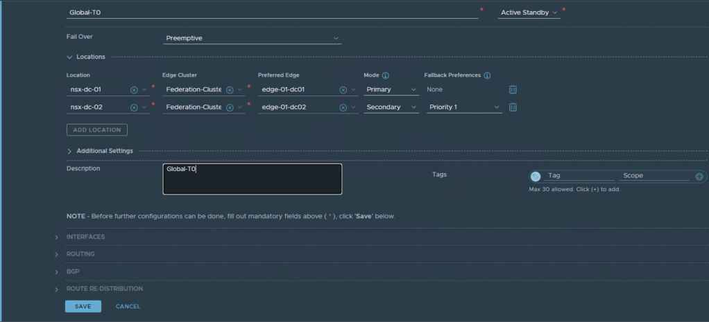
Once configured you can check if the T0 has been successfully configured across all locations as intended
Next we will configure the uplink interfaces on the T0 for each Edge VM – this will be used for the North/South traffic and the BGP Peering to the TOR. The interfaces are configured from the GM.
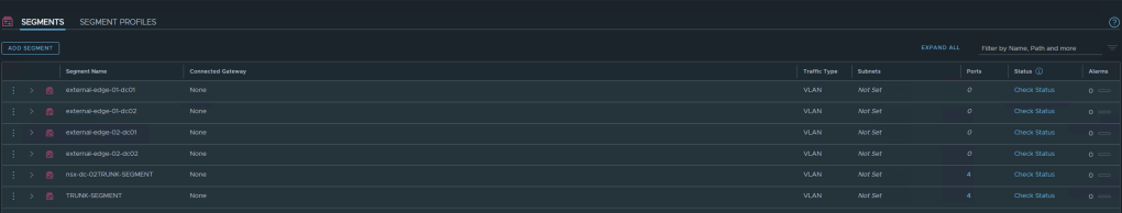
Before we proceed with adding the interfaces in the T0, I need to configure the segments which I will be using for the uplink interfaces. In my lab I will be using VLAN1331 and VLAN1332 in DC-01 and VLAN 2331 and VLAN 2332 in DC-02 as the uplink segments to my TOR.

Repeat this process for each Edge appliance uplink interface and remember to select the correct location for the segment and VLAN ID for this VLAN segment
Now I can proceed to map these VLAN backed segments as uplink interfaces in the GM TO
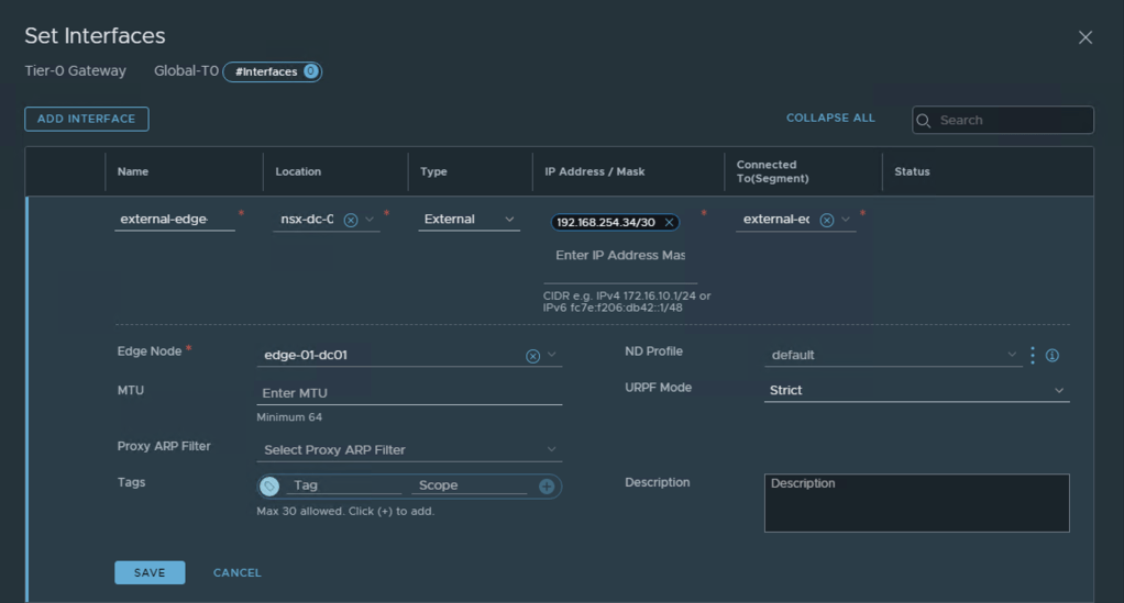
Remember to select the correct Location, Segment and Edge appliance for the IP address configured. Then repeat this for the required uplink interfaces on the T0 across both sites.
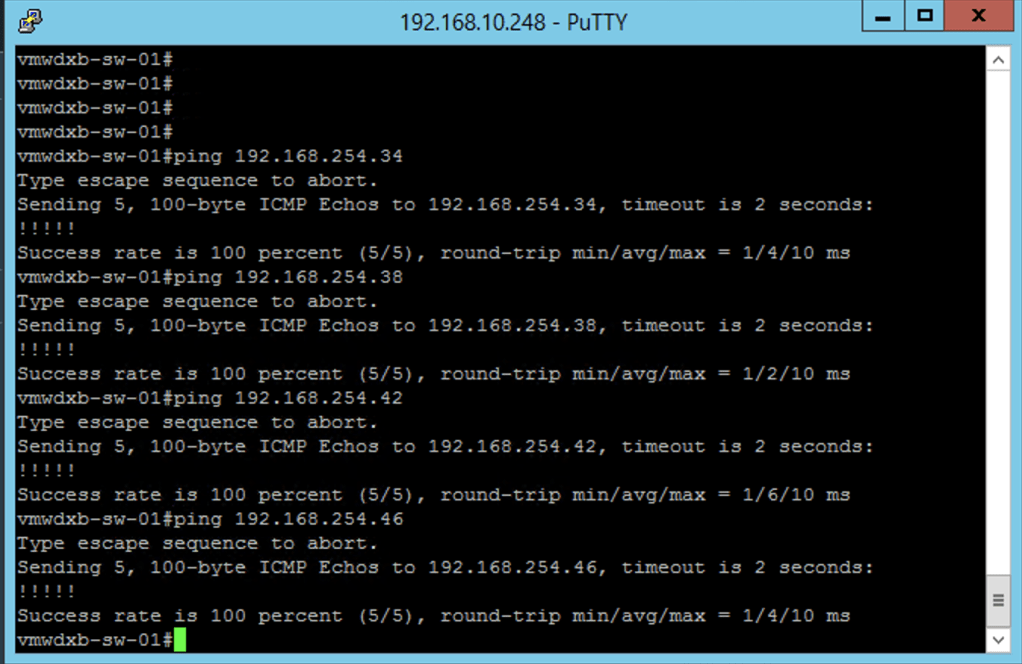
After doing the first interface I done a quick ping test from the directly connected TOR to confirm my connectivity is working as expected.
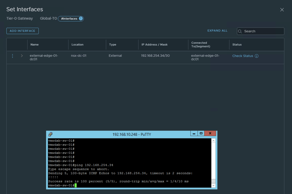
After configuring an external uplink interface for each of the Edge appliances my setup, I can see my Global T0 has 4 interfaces

Next will be to configure BGP Routing between the newly created Global T0 and the TOR.

I started by changing the default BGP Local AS number to 65333 and then went ahead to configure the BGP neighbours at the bottom right.
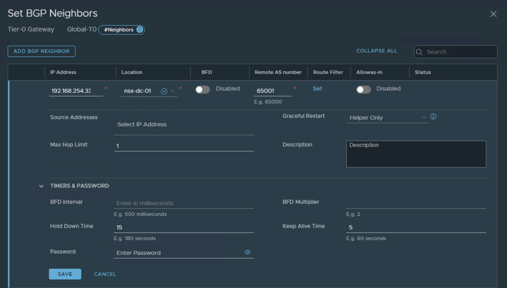
After adding the first BGP Neighbour in the Global T0, I confirmed that the BGP relationship has been established. Then repeated adding the rest of my BGP neighbours.

After all the BGP Neighbours have been configured, you should the status green and Successful. This can be confirmed from the TOR too.

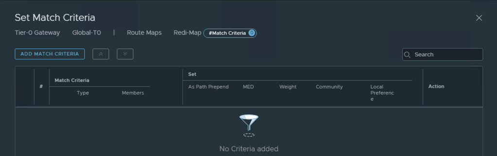
Route Redistribution in the T0
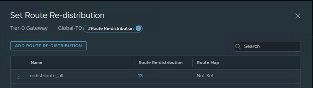
NSX-T provides extensive flexibility when deciding which networks would be redistributed upstream to the TOR, since this just a lab setup I will enable all networks created in my topology to redistributed and advertised to the TOR.
First start by creating redistribution list for each location

The redistribution list can be applied to Route Map where extended BGP attributes can be added:
Adding a Global T1 Router
Now that we have the North / South connectivity and routing up and running we will go ahead and create a T1 which will provide the default gateway connectivity for our networks and add some segments which will be stretched across the two NSX locations.

Adding Global Segments
Next step is creating Global Segments, these will be created as overlay Segments and attached to Global-T1 previously created. I will create three Global Segments for my Global 3 Tier Application.

As before, after configuring the first segment I want to confirm that BGP is now dynamically updating my TOR with the newly created Segement.
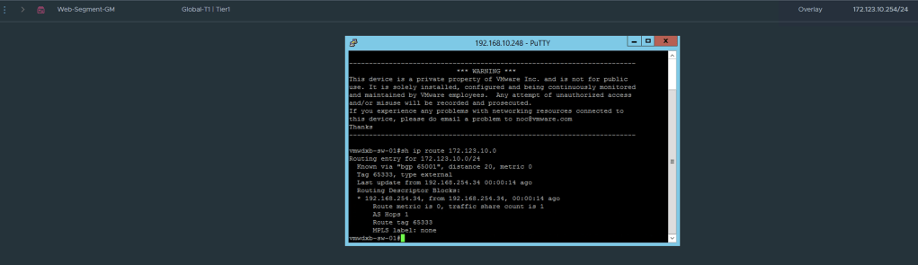
After completing the configurations for the three segments, I can see them successfully created in the GM dashboard.

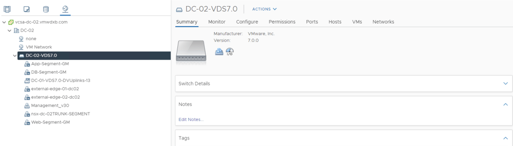
The newly created segments can all be seen in the vCenters at each location and can now be used to connect VM’s.
Once the VM’s have been connected to newly created Segments, we can test our connectivity.
Network Topology Overview
NSX-T 3.0 introduced a network topology view which is only available in the Local Managers

From the topology view you can see the T0, T1, uplink interfaces and segments created with their IP addresses and the VM’s connected to these segements.
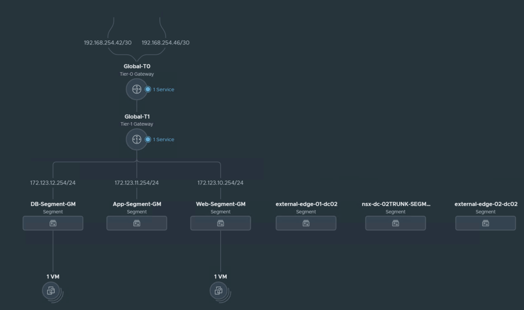
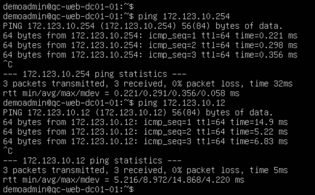
A quick ping test from WEB-01 deployed in DC-01 with IP 172.123.10.11 to the WEB-02 VM deployed in DC-02 with IP 172.123.10.12 shows our cross site connecitvity is working as expected.
In the next blog I will focus on adding Global Security Policies and enabled Micro-Segmented policies across the two sites centrally configured and managed in the Global Manager.
